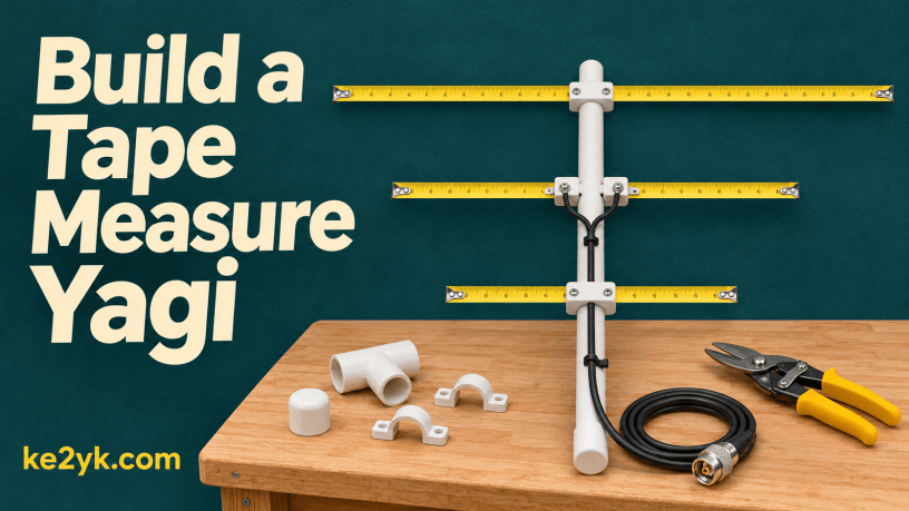
Make a lightweight beam from a steel tape measure and PVC, then check the whole setup before you take it into the field.
Want a directional antenna for a 2-meter fox hunt or your next summit outing? This guide shows you how to build a tape measure Yagi, check its coax, and test it on the air before you pack it.
Cold Fell and Cross Fell are mountain summits in the North Pennines of northern England. View a map of the North Pennines. A “fell” is a local word for a hill or mountain. M1TJM visited both for Summits on the Air (SOTA), an amateur radio award program. Operators called “activators” carry portable radio gear to qualifying summits and make contacts. Other hams, called “chasers,” try to contact them from home or another location. Both can earn points toward awards.
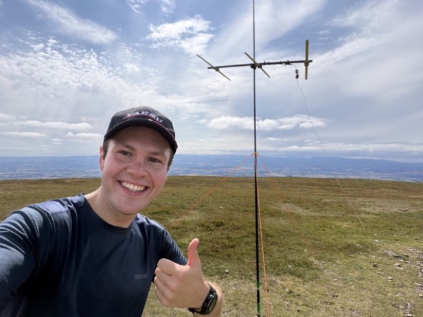
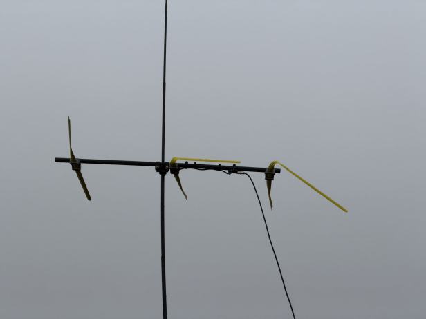
On Cold Fell, M1TJM’s homebuilt beam ran into two problems. Wind bent the elements, and the coax failed. The team switched to a vertical Slim Jim and reported a 354 km contact on 10 watts. Later that day on Cross Fell, M1TJM tried a different run of coax and made two 2-meter SSB contacts with the Yagi. Check the antenna and the cable together before the hike. Read M1TJM’s SOTA report.
1. Gather the parts and cut the elements
This build follows Joe Leggio, WB2HOL, who designed the beam for finding hidden transmitters. You’ll need a 1-inch-wide steel tape measure blade, ½-inch Schedule 40 PVC pipe, two matching crosses and one tee, stainless worm-drive hose clamps that fit the fittings, 50-ohm coax such as RG-58 with a connector for your radio, and 5 inches of solid wire for the matching loop. Use shears for the blade, a saw for the PVC, and a file or sandpaper for the edges and feed contacts.
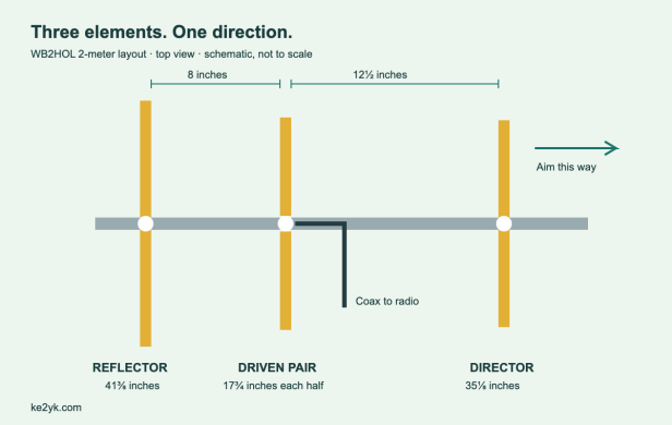
- Reflector, at the rear — one piece, 41⅜ inches.
- Driven element, in the middle — two pieces, 17¾ inches each.
- Director, at the front — one piece, 35⅛ inches.
Wear eye protection. Hold the spring steel firmly as you cut, round the corners, smooth the burrs, and cover the exposed outer ends with vinyl tape. Leave bare metal at the two inner feed contacts once you’ve sanded the paint off.
2. Assemble the PVC boom
Cut a 7-inch pipe section for the rear and an 11½-inch section for the front. Dry-fit a tee for the reflector at the back, a cross for the driven element in the middle, and a cross for the director at the front. The plan shows 8 inches from reflector center to driven-element center and 12½ inches from driven-element center to director center. Check those assembled distances before securing the boom, since fittings can seat at different depths.
Center the reflector and director on their fittings. Clamp the driven halves to opposite sides of the middle cross with about a 1-inch gap between their inner ends. Keep the three elements parallel and the driven halves equally spaced from the boom. Each driven half gets its own clamp. Point the front of the boom, where the short director sits, toward the station you want to hear.
3. Wire the feed point
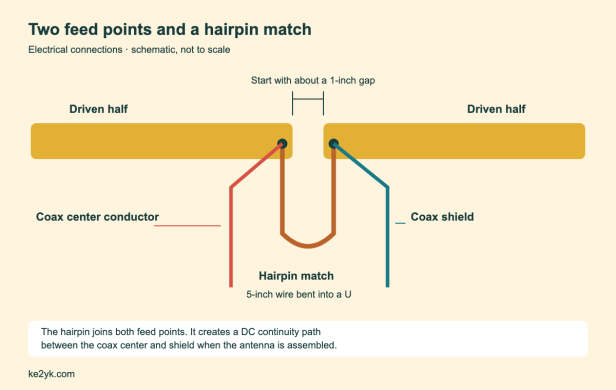
Connect the coax center conductor to one driven half and the shield to the other. Bend the 5-inch wire into a U with its legs about ¾ inch apart. Strip or scrape its ends, then connect one end to each of the same two feed points. This loop is the hairpin match. Start with the gap from the plan and leave the driven halves free to slide for tuning. You can use the clamps to hold the conductors against bare steel, or fasten terminals to the steel itself. If you solder to the blade, work away from the PVC.
Tie the coax to the boom with a little slack at the feed point so a tug on the cable can’t pull on the connections. Make sure stray braid strands can’t touch the center conductor. See WB2HOL’s original drawings and feed-point photo.
4. Check the coax and tune for your frequency
- Check the coax by itself. Disconnect it from the radio and the antenna. Use a multimeter to check center pin to center conductor and shell to shield. Each path should show continuity. The center and shield should be isolated from each other. Gently flex the cable at both ends and watch for a reading that jumps.
- Check the assembled feed point. Verify that each side of the coax reaches its own driven half before attaching the hairpin. Once the hairpin is in place, the meter can show continuity from the connector center to the shell because the U-shaped wire bridges them at DC.
- Measure SWR outdoors. With the radio disconnected, connect a 2-meter antenna analyzer or calibrated VNA at the radio end of the feed line you’ll take into the field. Set the antenna clear of metal and away from power lines. Check SWR at the frequency you plan to use, with the coax routed as it will be in use.
- Adjust the gap in small steps. Slide both driven halves by equal amounts, tighten the clamps, and measure again with your hands clear. If the readings jump when the cable moves, check the connections or swap in a known-good cable before adjusting further. Aim for a stable match within your radio’s limits at your operating frequency.
5. Try it on the air before you pack it
Ask a local ham to help with a simplex test on a clear frequency you may use. Start at low power. Hold the elements vertical for a station using a vertical antenna, as is common on FM. Turn the elements horizontal for a station using horizontal polarization, as is common on 2-meter weak-signal SSB. Keep the director pointed toward the other station, then turn the beam and compare reports at the same power. A low SWR tells you how well the system matches the radio. The signal check tells you how the setup works on that path.
Set the beam up once with the same mount, coax, and adapters you’ll carry. If wind folds the tape blades out of shape, switch to your backup antenna. A known-good spare coax jumper can also save the outing.
Related Reading
- Portable QRP Antenna Troubleshooting: Beyond 1:1 SWR
- Portable Power Wiring: How to Stop Voltage Drop
Follow Me on Mastodon
Have you built a tape measure beam? Share what worked for you at the bench or in the field. 73!
Discover more from KE2YK
Subscribe to get the latest posts sent to your email.

