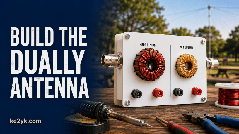
One compact board, two different impedance transformers: the K4QCD Dually gives portable operators a 49:1 path for a resonant end-fed half-wave and a 9:1 path for a non-resonant end-fed wire used with a tuner.
Portable HF antennas are always a compromise among size, setup time, band coverage, and the gear you’re willing to carry. Justin, K4QCD, approached that problem with the Dually antenna system: a compact, two-sided build that places a 49:1 unun and a 9:1 unun in one package.
Mike, K8MRD, walks through the original Dually build in the video below. His project adds a linked wire element that can serve as an end-fed half-wave on the 49:1 side or a 41-foot non-resonant wire on the 9:1 side. It’s a clever way to carry two useful antenna approaches without packing two separate matching units.
What the two sides actually do
The Dually isn’t one broadband matching circuit with a mode switch. Think of it as two separate antenna transformers sharing one compact physical assembly.
The 49:1 side: a resonant end-fed half-wave
The 49:1 transformer is intended for an end-fed half-wave, where the feed-point impedance is much higher than the 50-ohm input expected by most transceivers. K4QCD lists approximate radiator lengths of 33 or 65 feet for simple deployments. A wire cut for 40 meters may also present usable matches on harmonically related bands, but its final resonant points depend on wire insulation, height, configuration, nearby conductors, and ground conditions.
Start long and trim carefully while watching an antenna analyzer. A low reading on one frequency doesn’t guarantee good performance everywhere, so sweep every band segment you intend to use.
The 9:1 side: a non-resonant end-fed wire
The 9:1 transformer is intended to bring the widely varying impedance of a non-resonant wire closer to a range an antenna tuner can handle. K4QCD suggests approximate radiator lengths of 29 or 41 feet for this side. Mike’s linked-wire approach uses the 41-foot option.
A 9:1 unun is not a substitute for a tuner, and “random wire” shouldn’t mean a literally random length. Some lengths can place a very high impedance at the feed point on an amateur band, leaving an internal tuner unable to find a match. Treat published non-resonant lengths as starting points and confirm the system with an analyzer in the exact field configuration you plan to use.
Build sequence and details that matter
The official instructions contain the winding photos and board-specific hole labels, so keep them open while you work. At a high level, the project breaks into four stages:
- Wind and install the 49:1 transformer. Follow the photo orientation, leave workable wire tails, remove the enamel completely at each solder point, and install the supplied capacitor where the board marks it.
- Wind and install the 9:1 transformer. Keep the three conductors organized and uncrossed. The different wire colors help you preserve the correct start-to-finish connections.
- Add connectors and hardware. Solder the BNC connectors without dwelling so long that heat damages their internal insulation. Fit the bolts, lock nuts, and wing nuts in the orientation shown for your board revision.
- Inspect before sealing. Check continuity, verify that enamel hasn’t blocked a joint, confirm that there are no solder bridges, secure the toroids, and only then apply heat-shrink or final strain relief.
Toroid work rewards patience. Count a turn each time a conductor passes through the center of the core, keep the winding snug and orderly, and avoid nicking the enamel. When soldering, use ventilation, eye protection, and a heat-resistant work surface.
Tune the antenna as a complete system
Mike’s demonstration is useful because it follows the build into the part that often decides whether a portable antenna is enjoyable: adapting the radiator to the deployment. The transformer, radiator, counterpoise or return path, coax, common-mode choke, height, and geometry all interact.
For the 49:1 configuration, adjust the resonant wire in small steps and recheck the bands after every change. For the 9:1 configuration, connect the non-resonant wire and counterpoise arrangement you intend to carry, then confirm that your tuner can match each desired band. If the tuner struggles, don’t force it; change the radiator length or deployment and measure again.
K4QCD states that the antenna has been used at 100 watts SSB but does not specify a confirmed CW or digital-duty rating. Modes with a higher duty cycle can heat small transformers quickly, so use conservative power, monitor for heating, and follow the current maker guidance.
Who the Dually project suits
This build makes the most sense for an operator who enjoys soldering, wants to experiment with both resonant and tuner-assisted end-fed wires, and values flexibility in a small field kit. It’s especially appealing if you already carry an analyzer and tuner and don’t mind spending time dialing in wire lengths for your usual deployment.
If your priority is the fastest possible setup on a small set of bands, a dedicated, pre-tuned antenna may be simpler. The Dually’s payoff is choice: one compact project lets you learn the practical differences between two popular end-fed systems and select the one that fits the day’s operating plan.
Bottom line
The K4QCD Dually is a smart builder’s project because its versatility comes from two clearly defined tools rather than one magical “all-band” claim. Build carefully, use only one side at a time, and treat wire lengths as measured starting points. Mike K8MRD’s video supplies the workshop perspective; K4QCD’s current instructions should remain the final authority for your particular board.
Official resources
Follow Me on Mastodon
Discover more from KE2YK
Subscribe to get the latest posts sent to your email.

